
Let us take the below topology to understand the concept of trunking in switches.
In the below topology, we have total four PC devices. PC-1 and PC-3 are connected to access port of switch 1 and under VLAN 22 and 23 respectively. Similarly, PC-2 and PC-4 are connected to access port of switch 2 and under VLAN 22 and 23 respectively.
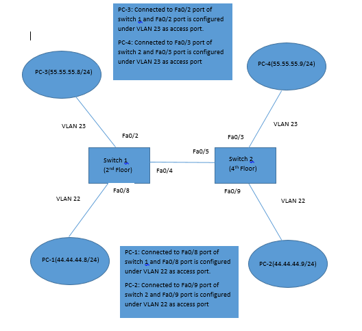
Let us say PC-1 wants to send a message to PC-2. Both are under VLAN 22(under same network: 44.44.44.0) but both the PCs are connected to different switches.
Below is the flow of messages happen b/w PC-1 and PC-2.
- Before sending the message, PC-1 check that it does not have MAC address of PC-2. To get the MAC address, PC-1 sends ARP request.
- Switch 1 receives the ARP request and found that this message need to broadcast since the destination MAC address is set to all FF in ARP request. Switch 1 then sends this message to all its VLAN 22 ports.
- The message should be send to switch 2 from port Fa0/4 as destination device is connected to switch 2. However, switch-2 should not send this broadcast message to PC-4 because it is under different VLAN. So how switch 2 come to know that the message is for VLAN 22.
- This tag is called 802.1Q Tag. Also, if the message contain specific destination MAC address instead of broadcast address, then switch-2 will send it to particular port of VLAN 22 based on the destination MAC address.
- Here comes the role of 802.1Q VLAN Trunking.
Switch-1 before sending the message on port Fa0/4 appends Tag (
VLAN ID) to tell to the switch-2 that the message is for VLAN 22.
Switch-2 on the other hand once receives the message, it check the Tag
value, remove it and then broadcast the message on that particular
VLAN ports.
Link connecting switch 1 and switch 2 is called a trunk.
This process is called trunking and protocol used is 802.1Q.
If we want to have communication b/w the switches so that message coming from one switch to another switch know to which VLAN it belongs to, we need to configure 802.1Q protocol on both ports of switches.
Below are the command used to configure 802.1 Q on the switches.
- We need to configure the ports that are connected b/w the switches as trunk ports.
* Go to configuration Mode for switch 1 using “conf” command.
* Interface Fa0/4 : With this command, it enters Fa0/4 port.
* switchport trunk encapsulation dot1q: This command tells that for
trunk port, 802.1Q protocol to be used for tagging.
* switchport mode trunk: configure the port as trunk port.
* Perform above steps on the port Fa0/5 of switch 2. - Above configuration can be verified by using “show interfaces trunk” command.
Switch 1 Output:
Port Mode Encapsulation Status Native VLAN
Fa0/4 on 802.1q trunking 1
Switch 2 Output:
Port Mode Encapsulation Status Native VLAN
Fa0/5 on 802.1q trunking 1